Apply Electrode Montage
Give each channel a scalp location
After importing the raw data, we have a matrix with one row per EEG channel. Applying an electrode montage connects those rows to scalp locations. Here, montage means the channel names and their three-dimensional coordinates. Attaching locations does not itself change the voltages or recording reference. MNE’s sensor-location guide explains this use of the term.
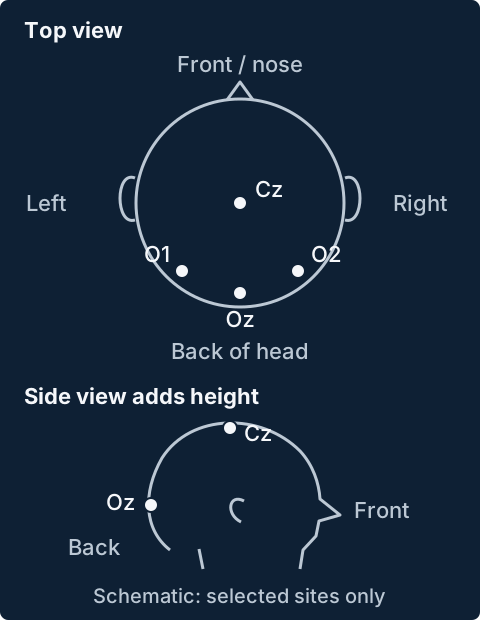
Think of a channel name as a label and its coordinates as an address. The software needs both to know where a measurement belongs. A flat drawing is useful for viewing electrodes, but the scalp is curved: the full position includes height as well as left–right and front–back information.
Use the montage that matches your recording
Different caps use different arrangements and naming conventions. These are a few examples:
- 10–20, 10–10 and 10–5 systems: positions are defined using proportional distances between head landmarks. The denser systems add sites between existing ones. Oostenveld and Praamstra (2001) explain the systems and illustrate their electrode labels.
- BioSemi caps: the manufacturer provides layouts and coordinate files for its caps. Its 64-channel layout uses familiar scalp labels, while its higher-density caps use radial arrangements with labels such as A1 and B1. Check the specific BioSemi cap layout used during acquisition.
- EGI HydroCel nets: these have their own sensor arrangements and numbered labels. FieldTrip’s electrode templates include several HydroCel configurations alongside other common systems.
Having the same number of channels does not make two montages interchangeable. Match the cap model, layout and channel labels to the recording using the manufacturer’s information or electrode templates. Templates approximate an arrangement; individually digitized positions describe where electrodes were measured on that participant’s head, as discussed by Oostenveld and Praamstra.
Why the three-dimensional positions matter
- Scalp maps: positions determine where each channel’s value is drawn. A misplaced or mirrored montage can make a response appear over the wrong part of the scalp. The familiar two-dimensional map is a projection of the three-dimensional sensor positions.
- Bad-channel interpolation: when estimating a bad channel from the remaining good channels, the software uses their spatial relationship. Incorrect locations therefore affect the estimate. MNE’s interpolation guide explains how sensor positions enter this calculation.
- Source estimates: if an analysis tries to estimate where activity arose inside the brain, electrode positions must be aligned with a head model. Coordinate or alignment errors can shift the estimated source. Akalin Acar and Makeig (2013) examine these errors. Coordinates alone do not identify a brain source.
A frequency spectrum can still be calculated separately for each channel without knowing its scalp coordinates. The locations become essential when interpreting where a response was measured or performing spatial operations. If O1 and O2 are assigned to the wrong recorded channels, for example, a left–right comparison would be reversed. Our Regions of Interest guide illustrates how channel labels relate to scalp regions.
Check the positions before continuing
Confirm each EEG channel’s label and location; treat eye, trigger and other auxiliary channels separately. Inspect front–back and left–right orientation, and missing or implausible positions, in top and three-dimensional views. MNE recommends plotting locations after applying a montage.
When importing a custom coordinate file, also check the units and coordinate frame: which way the axes point and where their origin lies. Millimetres and metres are not interchangeable, and different tools use different axis conventions. FieldTrip’s coordinate-system guide explains what must agree when combining electrodes with other head geometry.